
 FREE DELIVERY FOR ORDERS ABOVE $100 ALL AROUND SINGAPORE!
PRODUCTS
")
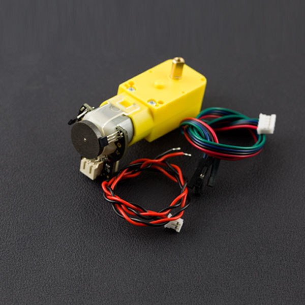
I-Shape - TT Motor with Encoder (6V 160RPM / 120:1)
MODEL: FIT0450
(per piece)


Specification
- Gear ratio: 120:1
- No-load speed @ 6V: 160 rpm
- No-load speed @ 3V: 60 rpm
- No-load current @ 6V: 0.17A
- No-load current @ 3V: 0.14A
- Max Stall current: 2.8A
- Max Stall torque: 0.8kgf.cm
- Rated torque: 0.2kgf.cm
- Encoder operating voltage: 4.5~7.5V
- Motor operating voltage: 3~7.5V (Rated voltage 6V)
- Operating ambient temperature: -10 ~ +60℃
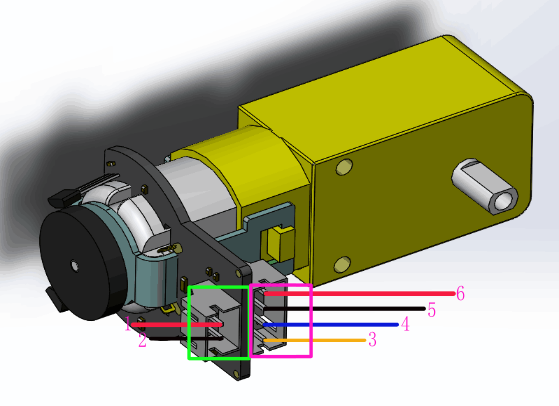
Pin Description
| Grade | Name | Functional Description |
|---|---|---|
| 1 | Motor power supply pin + | 3-7.5V,Rated voltage6V |
| 2 | Motor power supply pin - | |
| 3 | Encoder A phase output | Changes square wave with the output frequency of Motor speed |
| 4 | Encoder B phase output | Changes square wave with the output frequency of Motor speed(interrupt port) |
| 5 | Encoder supply GND | |
| 6 | Encoder supply + | 4.5-7.5V |
Tutorial
Requirements
- hardware
- Arduino UNO x1
- DC power supply x1
- L298 2x2A Motor Shield for Arduino Twin x1
- software
- Arduino IDE Download Arduino IDE
Connection Diagram
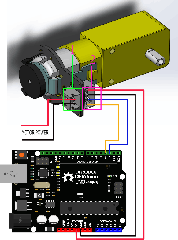
This tutorial is about Encoder usage. We are using D2&D3 as driving pins, you can select other ones, but it requires at least 1 interrupt pin. (We selected D2, Interrupt 0 in this tutorial).
Interrupt Port with Different Board
Notice: attachInterrupt()
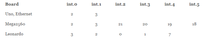
If using an Arduino UNO and you want to use interrupt port 0 (Int.0), you need to connect digital pin D2 on the board. The following code is only used in UNO and Mega2560. If you want to use Arduino Leonardo, you should change digital pin D3 instead of digital pin D2.
See the link for details http://arduino.cc/en/Reference/AttachInterrupt
Sample Code 1
Code 1 phenomenon:
Explanation: Serial data, when the motor forward, the output value> 0, when the motor reverse rotation, digital output <0. The faster the motor speed, the greater the absolute value of number.

Sample Code 2
PID control: PID algorithm to control the motor speed by L298P DC motor driver board
- Motor power port is connected to the L298 drive motor M1 port
- Download and install Arduino PID