FREE DELIVERY FOR ORDERS ABOVE $100 ALL AROUND SINGAPORE!
PRODUCTS

Me Color Sensor V1
MODEL: AE - MB11050
(per piece)
Me Color Sensor V1

Overview
The Me Color Sensor is a color sensor capable of recognizing a total of six colors, including black, white, red, blue, yellow, and green. This module’s interface port is a standard blue-and-white, and uses I2C protocol for communication. It must be directly connected to a motherboard with a blue-and-white interface port.
Technical specifications
● Operating voltage: 5V
● Operating current: <5mA
● Operating temperature: -20~60˚C
● Signal type: I2C
● Module dimensions: 48mm x 24 mm x 18 mm (LxWxH)
Functional characteristics
● The white region is a reference point for the attachment of the metal beam;
● Contains reverse current protection; reverse current will not damage the IC;
● Supports Arduino IDE programming and provides a runtime library to simplify programming;
● Supports mBlock graphics programming,suitable for users of all ages;
● Uses RJ25 cables for convenient connections;
● Offers modular installation, compatible with the Lego series.
Pin definition
The port of Me Color Sensor has six pins, and their functions are as follows: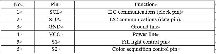
Wiring mode
● Connecting with RJ25
As the color sensor module has a blue-and-white interface, when using the RJ25 cables to create a connection, it will need to be connected to the blue-and-white labeled port of the motherboard. The picture below provides an example using Makeblock MegaPiPro, in which ports 6, 7, 8, 9, 10, 11, and 12 can all be used: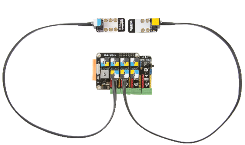
● Connecting with Dupont wire
When using a DuPont cable to connect to the Arduino Mega2560 motherboard, the module’s SCL and SDA pins must connect to the I2C port, and the S1 and S2 pins must be connected to the digital interface, which are the A10 and A11 ports, as shown in the picture below: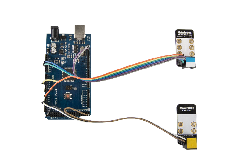
(The Arduino Mega2560 motherboard shown is not an officially registered product, please use with caution)
Guide to programming
● Arduino programming
If you use Arduino programming, you will need to use the Makeblock-Library- master runtime library to control the color sensor module. This program is written using Arduino; When using the color sensor to identify different colors, we can use the serial monitor to view the color data.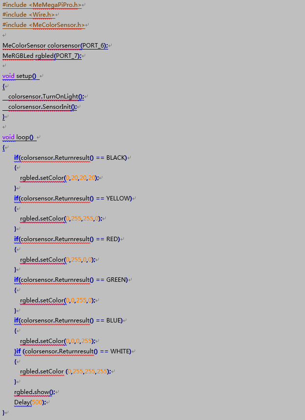
● mBlock programming
The color sensor module supports the mblock programming environment, and the module’s usage instructions are as follows: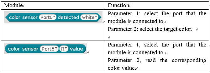
The following uses the LED module to display the color data collected by the color sensor:
Functional Analysis
The color sensor module contains an integrated BH1745NUC digital color sensor and uses time-division multiplexing to achieve multi-module parallel acquisition. It has a single-module conversion time of 160 mS. To reduce the effect of the indicator light on sensor functionality, the indicator light turns off when the sensor is turned on. The I2C bus is used to read the conversion results.
Control methods are as follows: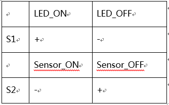
Turn on fill light: S1 = HIGH; Turn off fill light: S1 = LOW
Turn on sensor: S2 = LOW; Turn off sensor: S2 = HIGH
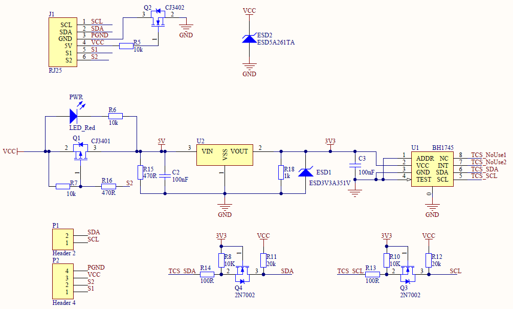
Schematic